Design of Self-Centring Moment Resisting Steel Frames: Preliminary Finite Element Analysis for Quasi-Static and Dynamic Tests
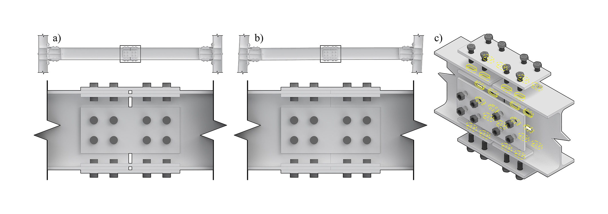
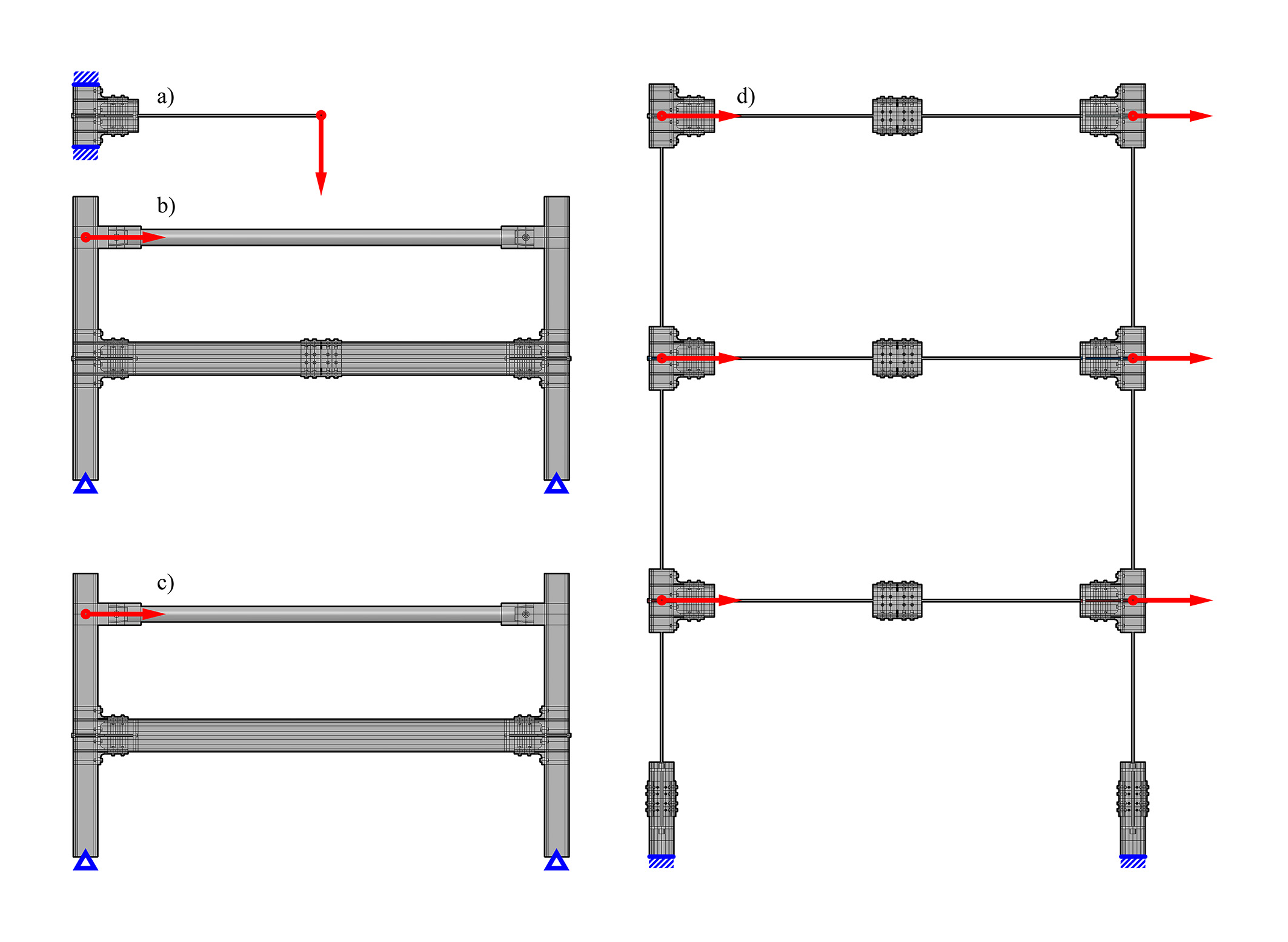
Through high-fidelity Finite Element Analysis (FEA), this research contributes to the design of Self-Centring Moment-Resisting Steel Frames (SC MRFs) for seismic resilience. As part of the SC-RESTEEL project, it focuses on validating the performance of novel Self-Centring Beam-to-Column Joints (SC BCJs) ahead of quasi-static tests and large-scale shaking table tests. To enhance the BCJ’s self-centring behaviour, beams are fitted with slotted splice connection at mid-span. Using solid and wire-part FE models in Abaqus, this study simulates joint and frame behaviour, assessing Moment-Rotation (M-R) relationships, self-centring capability, and plastic as well as frictional energy dissipation.
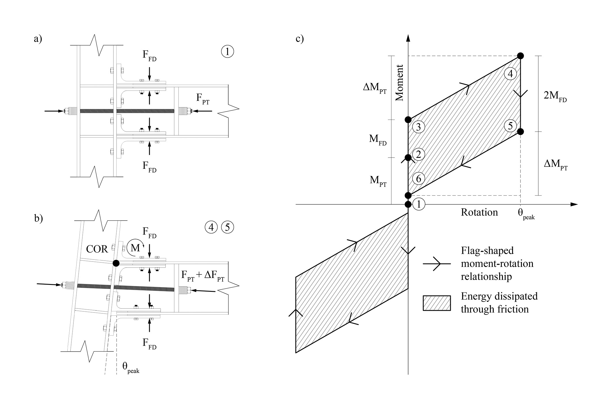
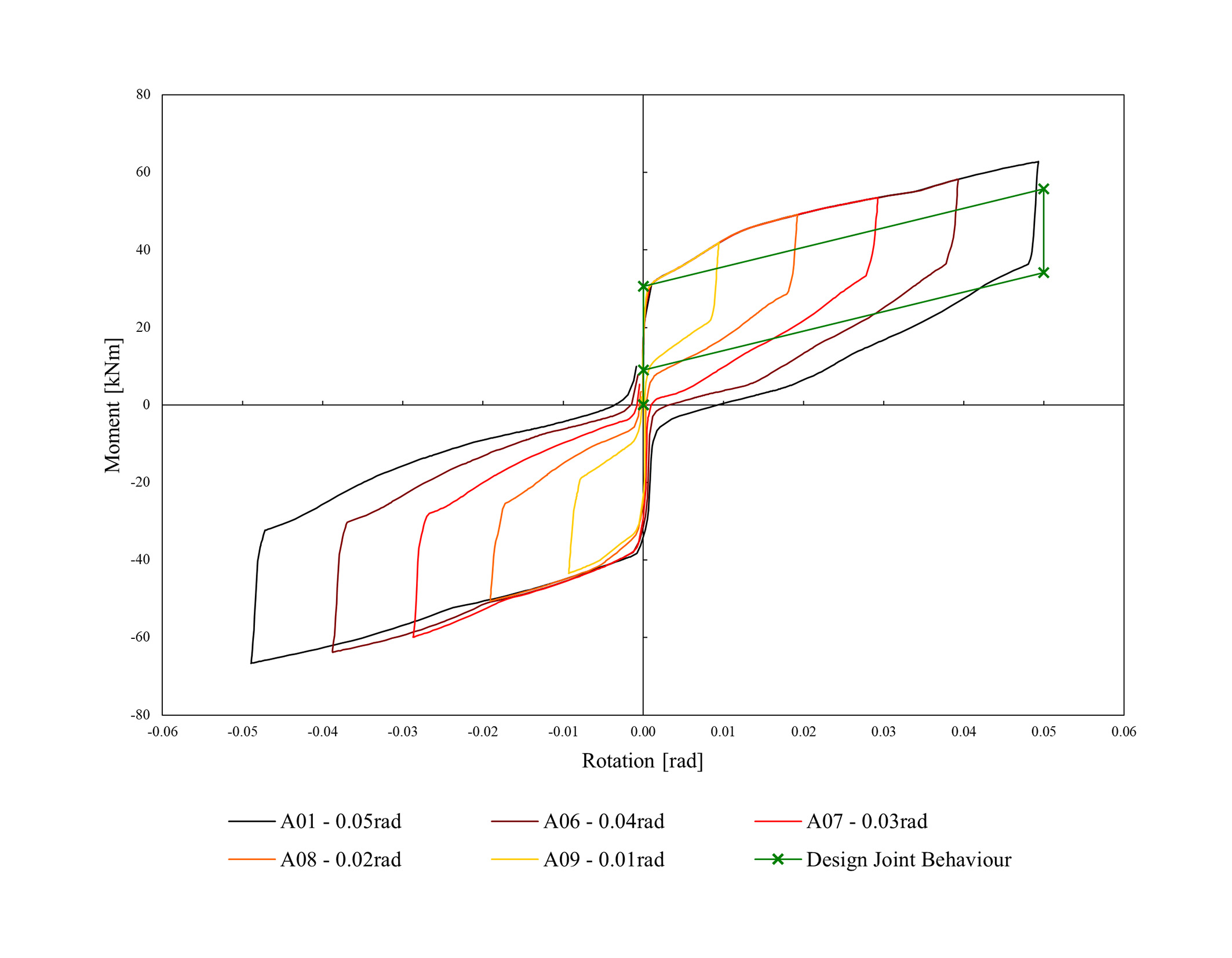
The study supports the development of SC BCJs for seismic zones through preliminary FEAs of physical test specimens. While FEA results of the BCJs’ local behaviour are promising, only the results for the quasi-static test specimens are conclusive. Results for the global response of the large-scale physical tests need further consideration. Local results indicate that the BCJ exhibits the expected flag-shaped M-R behaviour with good self-centring capabilities. At higher rotations, excessive plasticity in the L-plates and beam ends compromises self-centring. Frictional energy dissipation is primarily localised at the beam-end flanges, with smaller contributions from other surface interactions. Observed axial forces in friction device bolts exceed design values, increasing unintended frictional energy dissipation. Although material model variations have a limited impact on performance, using expected rather than nominal strengths improves self-centring. Slotted splice connections effectively mitigate the frame expansion effect at a frame level. Wire models prove computationally efficient with near-identical results.
This research contributed to a publication submitted to the 10th ECCOMAS Thematic Conference on Computational Methods in Structural Dynamics and Earthquake Engineering.